|
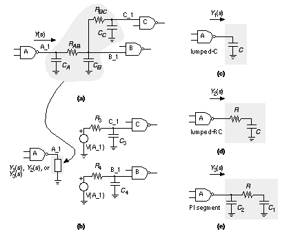
[ Chapter start ] [ Previous page ] [ Next page ] 17.4 Circuit Extraction and DRCAfter detailed routing is complete, the exact length and position of each interconnect for every net is known. Now the parasitic capacitance and resistance associated with each interconnect, via, and contact can be calculated. This data is generated by a circuit-extraction tool in one of the formats described next. It is important to extract the parasitic values that will be on the silicon wafer. The mask data or CIF widths and dimensions that are drawn in the logic cells are not necessarily the same as the final silicon dimensions. Normally mask dimensions are altered from drawn values to allow for process bias or other effects that occur during the transfer of the pattern from mask to silicon. Since this is a problem that is dealt with by the ASIC vendor and not the design software vendor, ASIC designers normally have to ask very carefully about the details of this problem. Table 17.2 shows values for the parasitic capacitances for a typical 1 m m CMOS process. Notice that the fringing capacitance is greater than the parallel-plate (area) capacitance for all layers except poly. Next, we shall describe how the parasitic information is passed between tools. 17.4.1 SPF, RSPF, and DSPFThe standard parasitic format ( SPF ) (developed by Cadence [ 1990], now in the hands of OVI) describes interconnect delay and loading due to parasitic resistance and capacitance. There are three different forms of SPF: two of them ( regular SPF and reduced SPF ) contain the same information, but in different formats, and model the behavior of interconnect; the third form of SPF ( detailed SPF ) describes the actual parasitic resistance and capacitance components of a net. Figure 17.22 shows the different types of simplified models that regular and reduced SPF support. The load at the output of gate A is represented by one of three models: lumped-C, lumped-RC, or PI segment. The pin-to-pin delays are modeled by RC delays. You can represent the pin-to-pin interconnect delay by an ideal voltage source, V(A_1) in this case, driving an RC network attached to each input pin. The actual pin-to-pin delays may not be calculated this way, however.
The key features of regular and reduced SPF are as follows:
Here is an example regular SPF file for just one net that uses the PI segment model shown in Figure 17.22 (e): #Capacitance Units : 1 pico farads # F <from CompName> <fromPinName> # T <toCompName> <toPinName> RC <rcConstant> A <value> # T <toCompName> <toPinName> RC <rcConstant> A <value> # TIMING.ADMITTANCE.MODEL = PI # TIMING.CAPACITANCE.MODEL = PP This file describes the following:
The reduced SPF ( RSPF) contains the same information as regular SPF, but uses the SPICE format. Here is an example RSPF file that corresponds to the previous regular SPF example: * Capacitance Units : 1 pico farads * TIMING.CAPACITANCE.MODEL = PP E1 DF1_G_INP1 VSS ROOT_Z VSS 1.0 E2 DF2_G_INP1 VSS ROOT_Z VSS 1.0 XDF1 DF1_Q DF1_QN DF1_D DF1_G DF1_CD DF1_VDD DF1_VSS DFF3 XDF2 DF2_Q DF2_QN DF2_D DF2_G DF2_CD DF2_VDD DF2_VSS DFF3 XROOT ROOT_Z ROOT_A ROOT_VDD ROOT_VSS BUF This file has the following features:
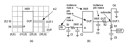
The detailed SPF ( DSPF) shows the resistance and capacitance of each segment in a net, again in a SPICE format. There are no models or assumptions on calculating the net delays in this format. Here is an example DSPF file that describes the interconnect shown in Figure 17.23 (a): *|I (INV1:A INV A I 0.0 10.0 5.0) *|I (INV:OUT INV1 OUT O 0.0 20.0 10.0) The nonstandard SPICE statements in DSPF are comments that start with '*|' and have the following formats: *|I(InstancePinName InstanceName PinName PinType PinCap X Y) *|P(PinName PinType PinCap X Y) Figure 17.23 (b) illustrates the meanings of the DSPF terms: InstancePinName , InstanceName , PinName , NetName , and SubNodeName . The PinType is I (for IN) or O (the letter 'O', not zero, for OUT). The NetCap is the total capacitance on each net. Thus for net IN, the net capacitance is 0.38 pF = C1 + C2 = 0.11 pF + 0.27 pF. This particular file does not use the pin capacitances, PinCap . Since the DSPF represents every interconnect segment, DSPF files can be very large in size (hundreds of megabytes). 17.4.2 Design ChecksASIC designers perform two major checks before fabrication. The first check is a design-rule check ( DRC ) to ensure that nothing has gone wrong in the process of assembling the logic cells and routing. The DRC may be performed at two levels. Since the detailed router normally works with logic-cell phantoms, the first level of DRC is a phantom-level DRC , which checks for shorts, spacing violations, or other design-rule problems between logic cells. This is principally a check of the detailed router. If we have access to the real library-cell layouts (sometimes called hard layout ), we can instantiate the phantom cells and perform a second-level DRC at the transistor level. This is principally a check of the correctness of the library cells. Normally the ASIC vendor will perform this check using its own software as a type of incoming inspection. The Cadence Dracula software is one de facto standard in this area, and you will often hear reference to a Dracula deck that consists of the Dracula code describing an ASIC vendor’s design rules. Sometimes ASIC vendors will give their Dracula decks to customers so that the customers can perform the DRCs themselves. The other check is a layout versus schematic ( LVS ) check to ensure that what is about to be committed to silicon is what is really wanted. An electrical schematic is extracted from the physical layout and compared to the netlist. This closes a loop between the logical and physical design processes and ensures that both are the same. The LVS check is not as straightforward as it may sound, however. The first problem with an LVS check is that the transistor-level netlist for a large ASIC forms an enormous graph. LVS software essentially has to match this graph against a reference graph that describes the design. Ensuring that every node corresponds exactly to a corresponding element in the schematic (or HDL code) is a very difficult task. The first step is normally to match certain key nodes (such as the power supplies, inputs, and outputs), but the process can very quickly become bogged down in the thousands of mismatch errors that are inevitably generated initially. The second problem with an LVS check is creating a true reference. The starting point may be HDL code or a schematic. However, logic synthesis, test insertion, clock-tree synthesis, logical-to-physical pad mapping, and several other design steps each modify the netlist. The reference netlist may not be what we wish to fabricate. In this case designers increasingly resort to formal verification that extracts a Boolean description of the function of the layout and compare that to a known good HDL description. 17.4.3 Mask PreparationFinal preparation for the ASIC artwork includes the addition of a maskwork symbol (M inside a circle), copyright symbol (C inside a circle), and company logos on each mask layer. A bonding editor creates a bonding diagram that will show the connection of pads to the lead carrier as well as checking that there are no design-rule violations (bond wires that are too close to each other or that leave the chip at extreme angles). We also add the kerf (which contains alignment marks, mask identification, and other artifacts required in fabrication), the scribe lines (the area where the die will be separated from each other by a diamond saw), and any special hermetic edge-seal structures (usually metal). The final output of the design process is normally a magnetic tape written in Caltech Intermediate Format ( CIF , a public domain text format) or GDSII Stream (formerly also called Calma Stream, now Cadence Stream), which is a proprietary binary format. The tape is processed by the ASIC vendor or foundry (the fab ) before being transferred to the mask shop . If the layout contains drawn n -diffusion and p -diffusion regions, then the fab generates the active (thin-oxide), p -type implant, and n -type implant layers. The fab then runs another polygon-level DRC to check polygon spacing and overlap for all mask levels. A grace value (typically 0.01 m m) is included to prevent false errors stemming from rounding problems and so on. The fab will then adjust the mask dimensions for fabrication either by bloating (expanding), shrinking, and merging shapes in a procedure called sizing or mask tooling . The exact procedures are described in a tooling specification . A mask bias is an amount added to a drawn polygon to allow for a difference between the mask size and the feature as it will eventually appear in silicon. The most common adjustment is to the active mask to allow for the bird’s beak effect , which causes an active area to be several tenths of a micron smaller on silicon than on the mask. The mask shop will use e-beam mask equipment to generate metal (usually chromium) on glass masks or reticles . The e-beam spot size determines the resolution of the mask-making equipment and is usually 0.05 m m or 0.025 m m (the smaller the spot size, the more expensive is the mask). The spot size is significant when we break the integer-lambda scaling rules in a deep-submicron process. For example, for a 0.35 m m process ( l = 0.175 m m), a 1.5 l separation is 0.525 m m, which requires more expensive mask-making equipment with a 0.025 m m spot size. For critical layers (usually the polysilicon mask) the mask shop may use optical proximity correction ( OPC ), which adjusts the position of the mask edges to allow for light diffraction and reflection (the deep-UV light used for printing mask images on the wafer has a wavelength comparable to the minimum feature sizes). [ Chapter start ] [ Previous page ] [ Next page ] | |||||||||||||||||||||||||||||||||||||||||||||||||||


