|
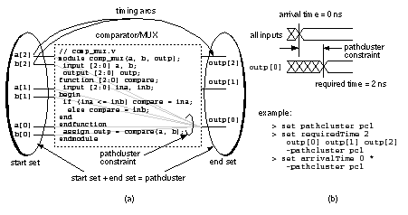
[ Chapter start ] [ Previous page ] [ Next page ] 12.11 Performance-Driven SynthesisMany logic synthesizers allow the use of directives. The pseudocomment in the following code directs the logic synthesizer to minimize the delay of an addition: module add_directive (a, b, z); input [3:0] a, b; output [3:0] z; These directives become complicated when we need to describe complex timing constraints. Figure 12.7 (a) shows an example of a more flexible method to measure and specify delay using timing arcs (or timing paths). Suppose we wish to improve the performance of the comparator/MUX example from Section 12.2 . First we define a pathcluster (a group of circuit nodes—see Figure 12.7 b). Next, we specify the required time for a signal to reach the output nodes (the end set ) as 2 ns. Finally, we specify the arrival time of the signals at all the inputs as 0 ns. We have thus constrained the delay of the comparator/MUX to be 2 ns—measured between any input and any output. The logic-optimization step will simplify the logic network and then map it to a cell library while attempting to meet the timing constraints.
Table 12.11 shows the results of a timing-driven logic optimization for the comparator/MUX. Comparing these results with the default optimization results shown in Table 12.3 reveals that the timing has dramatically improved (critical path delay was 2.43 ns with default optimization settings, and the delay varies between 0.31 ns and 1.64 ns for the timing-driven optimization).
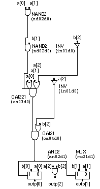
Figure 12.8 shows that timing-driven optimization and the subsequent mapping have simplified the logic considerably. For example, the logic for outp[2] has been reduced to a two-input AND gate. Using sis reveals how optimization works in this case. Table 12.12 shows the equations for the intermediate signal sel and the three comparator/MUX outputs in the BLIF. Thus, for example, the following line of the BLIF code in Table 12.12 (the first line following .names a0 b0 a1 b1 a2 b2 sel ) includes the term a0·b0'·a1'·b1'·a2'·b2' in the equation for sel : There are six similar lines that describe the six other product terms for sel . These seven product terms form a cover for sel in the Karnaugh maps of Figure 12.5 .
In addition sis must be informed of the don’t care values (called the external don’t care set ) in these Karnaugh maps. This is the function of the PLA-format input that follows the .exdc line. Now sis can simplify the equations including the don’t care values using a standard script, rugged.script , that contains a sequence of sis commands. This particular script uses a series of factoring and substitution steps. The output ( Table 12.12 ) reveals that sis finds the same equation for outp[2] (named outp2 in the sis equations): The other logic equations in Table 12.12 that sis produces are also equivalent to the logic in Figure 12.8 . The technology-mapping step hides the exact details of the conversion between the internal representation and the optimized logic.
1. See footnote 1 in Table 12.3 for explanations of the abbreviations used in this table. [ Chapter start ] [ Previous page ] [ Next page ] | |||||||||||||||||||||||||


