|
[ Chapter start ] [ Previous page ] [ Next page ] 9.5 CFI Design RepresentationThe CAD Framework Initiative ( CFI ) is an independent nonprofit organization working on the creation of standards for the electronic CAD industry. One of the areas in which CFI is working is the definition of standards for design representation ( DR ). The CFI 1.0 standard [ CFI, 1992] has tackled the problems of ambiguity in the area of definitions and terms for schematics by defining an information model ( IM ) for electrical connectivity information. What this means is that a group of engineers got together and proposed a standard way of using the terms and definitions that we have discussed. There are good things and bad things about standards, and one aspect of the CFI 1.0 DR standard illustrates this point. A good thing about the CFI 1.0 DR standard is that it precisely defines what we mean by terms and definitions in schematics, for example. A bad thing about the CFI DR standard is that in order to be precise it introduces yet more terms that are difficult to understand. A very brief discussion of the CFI 1.0 DR standard is included here, at the end of this chapter, for several reasons:
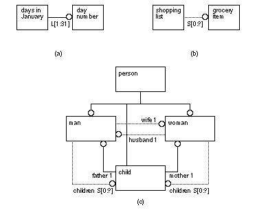
9.5.1 CFI Connectivity ModelThe CFI connectivity model is defined using the EXPRESS language and its graphical equivalent EXPRESS-G . EXPRESS is an International Standards Organization (ISO) standard [ EXPRESS, 1991]. EDIF 3 0 0 and higher also use EXPRESS as the internal formal description of the language. EXPRESS is used to define objects and their relationships. Figure 9.11 shows some simple examples of the EXPRESS-G notation.
The following EXPRESS code (a schema ) is equivalent to the EXPRESS-G family model shown in Figure 9.11 (c): ABSTRACT SUPERTYPE OF (ONEOF (man, woman, child)); This EXPRESS description is a formal way of saying the following:
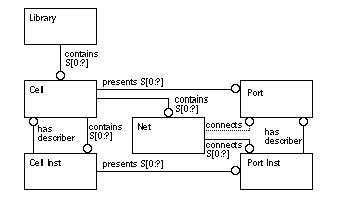
Computers can deal more easily with the formal language version of these statements. The formal language and graphical forms are more precise for very complex models. Figure 9.12 shows the basic structure of the CFI 1.0.0 Base Connectivity Model ( BCM ). The actual EXPRESS-G diagram for the BCM defined in the CFI 1.0.0 standard is only a little more complicated than Figure 9.12 (containing 21 boxes or types rather than just six). The extra types are used for bundles (a group of nets) and different views of cells (other than the netlist view).
Figure 9.12 says the following (“presents” as used in Figure 9.12 is the Express jargon for “have”):
Once you understand Figure 9.12 you will see that it replaces the first half of this chapter. Unfortunately you have to read the first half of this chapter to understand Figure 9.12 . [ Chapter start ] [ Previous page ] [ Next page ] | ||||


